

As a supplier of N male crimp connectors, ensuring the electrical performance of our products is of utmost importance. In this blog post, I will share with you the steps and methods I use to verify the electrical performance of N male crimp connectors.
Understanding the Key Electrical Parameters
Before we start the verification process, it's crucial to understand the key electrical parameters that define the performance of N male crimp connectors. These parameters include impedance, insertion loss, return loss, and voltage standing wave ratio (VSWR).
- Impedance: Impedance is a measure of the opposition to the flow of alternating current in a circuit. For N male crimp connectors, the standard impedance is typically 50 ohms. Maintaining the correct impedance is essential for minimizing signal reflections and ensuring efficient power transfer.
- Insertion Loss: Insertion loss refers to the amount of signal power that is lost when a signal passes through the connector. A lower insertion loss indicates better signal transmission.
- Return Loss: Return loss measures the amount of signal power that is reflected back from the connector. A higher return loss means less signal reflection and better impedance matching.
- VSWR: VSWR is a ratio that compares the maximum and minimum voltage along a transmission line. A lower VSWR indicates better impedance matching and less signal reflection.
Verification Methods
1. Visual Inspection
The first step in verifying the electrical performance of N male crimp connectors is a visual inspection. This involves checking the physical condition of the connector, including the crimp quality, the integrity of the outer conductor, and the alignment of the center conductor. Any visible damage or defects can significantly affect the electrical performance of the connector.
- Crimp Quality: Ensure that the crimp is tight and secure, with no visible gaps or loose wires. A poor crimp can lead to increased resistance and signal loss.
- Outer Conductor Integrity: Check for any signs of damage or corrosion on the outer conductor. A damaged outer conductor can cause signal leakage and interference.
- Center Conductor Alignment: Make sure the center conductor is straight and properly aligned. Misaligned center conductors can result in impedance mismatches and signal reflections.
2. Impedance Testing
Impedance testing is a critical step in verifying the electrical performance of N male crimp connectors. This can be done using an impedance analyzer or a network analyzer.
- Impedance Analyzer: An impedance analyzer measures the impedance of the connector at a specific frequency. By comparing the measured impedance with the standard impedance of 50 ohms, we can determine if the connector meets the required specifications.
- Network Analyzer: A network analyzer can measure both the insertion loss and return loss of the connector over a wide range of frequencies. This provides a more comprehensive assessment of the connector's electrical performance.
3. Insertion Loss and Return Loss Testing
Insertion loss and return loss testing are essential for evaluating the signal transmission and reflection characteristics of N male crimp connectors. These tests can be performed using a network analyzer.
- Insertion Loss Testing: To measure the insertion loss, a test signal is sent through the connector, and the power of the signal at the input and output is measured. The difference in power between the input and output is the insertion loss.
- Return Loss Testing: Return loss testing involves sending a test signal towards the connector and measuring the power of the reflected signal. The ratio of the reflected power to the incident power is the return loss.
4. VSWR Testing
VSWR testing is used to evaluate the impedance matching of N male crimp connectors. A VSWR meter or a network analyzer can be used to measure the VSWR of the connector.
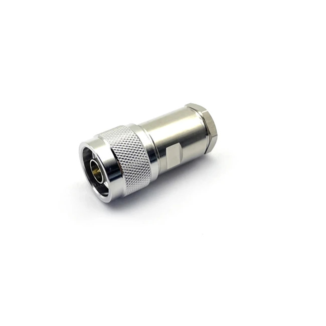

- VSWR Meter: A VSWR meter measures the VSWR of the connector at a specific frequency. A VSWR value close to 1 indicates good impedance matching, while a higher VSWR value indicates poor impedance matching.
- Network Analyzer: A network analyzer can measure the VSWR of the connector over a wide range of frequencies, providing a more detailed assessment of the connector's impedance matching performance.
Using Test Fixtures and Calibration
To ensure accurate and reliable test results, it's important to use proper test fixtures and calibration procedures.
- Test Fixtures: Test fixtures are used to hold the N male crimp connectors in place during testing. They should be designed to minimize signal reflections and interference.
- Calibration: Calibration is the process of adjusting the test equipment to ensure accurate measurements. Before performing any tests, the test equipment should be calibrated using a known reference standard.
Real - World Applications and Product Examples
In real - world applications, N male crimp connectors are widely used in various industries, such as telecommunications, aerospace, and military. Our company offers a range of high - quality N male crimp connectors, including RF Connector N Male for 5D - FB Cable Clamp Type N - J5, N Female Connector Panel Mount N - KFD, and RF Connector N Male Right Angle for 5D - FB Cable Clamp Type N - JW5.
These connectors are designed to meet the highest standards of electrical performance and reliability. By following the verification methods described above, we can ensure that our products meet the specific requirements of our customers.
Conclusion and Call to Action
Verifying the electrical performance of N male crimp connectors is a complex but essential process. By understanding the key electrical parameters, using proper verification methods, and ensuring accurate calibration, we can provide high - quality connectors that meet the needs of our customers.
If you are in the market for N male crimp connectors or have any questions about our products, we invite you to contact us for a detailed discussion. We are committed to providing the best solutions for your specific requirements.
References
- "RF Connector Handbook", published by a leading industry organization.
- Technical documents provided by connector manufacturers.